https://dseu.ac.in/faculties/s-deivanai/
Ph. D. (pursuing) – Friction Stir Welding, Indira Gandhi Delhi Technical University for Women, New Delhi;
M. Tech. – Production Engineering, Delhi Technological University, New Delhi;
B.E – Mechanical Engineering, Institute of Road and Transport Technology, Erode;
Courses teaching :
Manufacturing Technology;
Material Science;
Engineering Graphics;
Machine Drawing;
Metrology and Instrumentation;
CNC machines;
Basics of Automobile Engineering;
BEG – WEEK 2 SESSION 1
STUDY MATERIALS
Syllabus
ü 1. Demonstrate
the dimensioning and its necessity, methods, and principles,
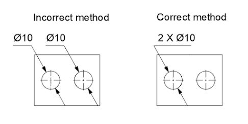
ü 2. Sheet no.2 Dimensioning of overall sizes, circles,
threaded holes, chamfered surfaces, angles, tapered surfaces, holes, equally
spaced on P.C.D., countersunk holes, counterbored holes, cylindrical parts,
narrow spaces and gaps, radii, curves, and arches.
Principles of Dimensioning
The following are the basic principles of dimensioning:
1. All dimensional information necessary to define a part clearly and
completely shall be shown directly on a drawing.
2. Each feature shall be dimensioned once only on a drawing.
3. Dimensions shall be placed on the view or section that shows clearly,
the corresponding features
4. As far as possible, on a drawing, dimensions should be
expressed in one unit only, preferably in millimeters, without showing the unit
symbol (mm). Unit on the drawing, however, may be shown in a note
5. No more dimensions than are necessary to define a part
shall be shown on the drawing. No feature of a part shall be defined by more
than one dimension in any one direction


https://dseu.ac.in/faculties/s-deivanai/
Ph. D. (pursuing) – Friction Stir Welding, Indira Gandhi Delhi Technical University for Women, New Delhi;
M. Tech. – Production Engineering, Delhi Technological University, New Delhi;
B.E – Mechanical Engineering, Institute of Road and Transport Technology, Erode;
Courses teaching :
Manufacturing Technology;
Material Science;
Engineering Graphics;
Machine Drawing;
Metrology and Instrumentation;
CNC machines;
Basics of Automobile Engineering;
Lines and Material conventions
1. Demonstration of various lines and material conventions
2. Sheet no 1. Draw the conventions of lines and materials
When you are preparing drawings, you will use different types of lines to convey information. Line characteristics, such as widths, breaks in the line, and zigzags, all have definite meanings.
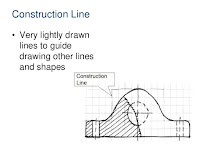
Construction Lines
Usually, the first lines that you will use on a drawing are construction lines. These are the same lines that you used to layout your drafting sheet. They will also be used to layout the rest of your drawing. Line weight for construction lines is not important since they will not appear on your finished drawing. They should be heavy enough to see, but light enough to erase easily. A 4H to 6H pencil with a sharp, conical point should be used. With the exception of light lettering guidelines, all construction lines must be erased or darkened before a drawing is reproduced


 https://dseu.ac.in/faculties/s-deivanai/
Ph. D. (pursuing) – Friction Stir Welding, Indira Gandhi Delhi Technical University for Women, New Delhi;
M. Tech. – Production Engineering, Delhi Technological University, New Delhi;
B.E – Mechanical Engineering, Institute of Road and Transport Technology, Erode;
Courses teaching :
Manufacturing Technology;
Material Science;
Engineering Graphics;
Machine Drawing;
Metrology and Instrumentation;
CNC machines;
Basics of Automobile Engineering;
https://dseu.ac.in/faculties/s-deivanai/
Ph. D. (pursuing) – Friction Stir Welding, Indira Gandhi Delhi Technical University for Women, New Delhi;
M. Tech. – Production Engineering, Delhi Technological University, New Delhi;
B.E – Mechanical Engineering, Institute of Road and Transport Technology, Erode;
Courses teaching :
Manufacturing Technology;
Material Science;
Engineering Graphics;
Machine Drawing;
Metrology and Instrumentation;
CNC machines;
Basics of Automobile Engineering;


| Type of Drawing Board | Length X Width X Thickness (mm) |
| D0 | 1500 X 1000 X 25 |
| D1 | 1000 X 700 X 25 |
| D2 | 700 X 500 X 15 |
| D3 | 500 X 350 X 15 |


| Grade of Pencil | Hardness of Pencil |
| 9H | Hardest |
| 6H, 5H, 4H | Extremely Hard |
| 3H | Very hard |
| 2H | Hard |
| H | Moderately hard |
| F | Firm |
| HB | Medium-hard |
| B | Moderately soft and black |
| 2B | Soft and black |
| 3B | Very soft and black |
| 4B, 5B, 6B | Very soft and very black |
| 7B | Softest |
| Grade of Pencil | Used to Draw |
| 3H | Construction lines |
| 2H | Dimension lines, centerlines, sectional lines, hidden lines |
| H | Object lines, lettering |
| HB | Dimensioning, boundary lines |


|
Setting up the mini drafter and drawing sheet. |


 https://dseu.ac.in/faculties/s-deivanai/
Ph. D. (pursuing) – Friction Stir Welding, Indira Gandhi Delhi Technical University for Women, New Delhi;
M. Tech. – Production Engineering, Delhi Technological University, New Delhi;
B.E – Mechanical Engineering, Institute of Road and Transport Technology, Erode;
Courses teaching :
Manufacturing Technology;
Material Science;
Engineering Graphics;
Machine Drawing;
Metrology and Instrumentation;
CNC machines;
Basics of Automobile Engineering;
https://dseu.ac.in/faculties/s-deivanai/
Ph. D. (pursuing) – Friction Stir Welding, Indira Gandhi Delhi Technical University for Women, New Delhi;
M. Tech. – Production Engineering, Delhi Technological University, New Delhi;
B.E – Mechanical Engineering, Institute of Road and Transport Technology, Erode;
Courses teaching :
Manufacturing Technology;
Material Science;
Engineering Graphics;
Machine Drawing;
Metrology and Instrumentation;
CNC machines;
Basics of Automobile Engineering;