Technical Lettering
Syllabus:
|
1. Introduction to lettering and its necessity.
Demonstrate the construction details of English alphabets and numerals in 7:4
ratio and free hand in parallel lines 2. Sheet no.3 practice of single
stroke vertical English alphabets and numerals (0-9) – uppercase letters
(Height14mm and 20mm lettering in 7:4 ratio) in single stroke Sheet no.4 practice of single stroke inclined English alphabets and numerals (0-9) – uppercase letters (Height14mm and 20mm lettering in 7:4 ratio) |
INTRODUCTION
https://youtu.be/bsutdDrPrKw
Technical Lettering is a barren piece
of engineering drawing. It gives data concerning measures, and
guidelines, as notes and measurements. On a drawing, the entire of the composed
data is consistently through lettering. It isn't manually written. Likewise, it
very well might be added here, that Lettering is fitting and right words
however not (Printing implies the creation of literature on a print machine)
·
Lettering
The writing of alphabets and numerals
such as A, B, C, D…………………….Z and 1, 2, 3……………9, 0 respectively is called Lettering.
Mainly, there are two types of
lettering most commonly used in engineering drawing viz. Gothic Lettering and
Roman Lettering.
Single Stroke Letters
The vertical letters are used for general purpose lettering in engineering drawing. Height to width ratio of such letters varies. But for all practical purposes the letters with height to width ratio may be taken as 7:5 or 6:5 for all capital letters except I, J, L, M and W. For M and W the suitable ratio is 10:8 and for I, this ratio is taken as 10:2. For numerals such ratio may be taken as 7:4 or 6:3. Single stroke vertical upper and lower case letters and numerals are shown in Fig. 1.17. The inclined/italics letters are written


·
Height Of Lettering
The height "h" of the capital
letter is taken as the base of dimensioning.
The main requirement of lettering on engineering drawing are legibility,
uniformity, ease and rapidity in execution.
Both upright and inclined letter are suitable for general use. All letters
should be capital, except where lower case letters are accepted internationally
for abbreviations.
The recommended size of lettering is as under :-
|
ITEM |
SIZE h, mm |
|
Drawing number in Title Block and letters denoting
Cutting Plane Section |
10, 12 |
|
Title of Drawing |
6, 8 |
|
Sub-titles and Headings |
3, 4, 5, 6, |
|
Notes, such as Legends, Schedules, Material list,
Dimensioning |
3, 4, 5 |
|
Alteration, Enteries and Tolerances |
2, 3 |
·
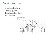
Guide Lines
The light thin lines drawn to obtain
uniform and correct height of letters are called Guide Lines.
Guide line should be drawn very light and thin, so that, they need not be
erased after the lettering is finished. To erase guide lines after finishing
the lettering is not easily possible. Guide line for capital and lower case
lettering
·
How To Draw Graph For Lettering
The letters are drawn in a graph.
Before drawing the alphabets or numerals of 7:4, 5:4 or any other ratio, a
graph is needed.
·
First of all take the height of the
lettering and draw two parallel horizontal lines.
·
Draw an inclined line at A and mark, 7 or 5
or as required number of vertical squares or rhombii, parts of any suitable
size. Join B1 with B.
·
Draw parallel line to B1B from 1, 2, 3, 4, 5,
6 meeting the line AB at A1, A2, A3, A4, A5 and A6.
·
From A1, A2, A3, A4, A5 and A6 draw
horizontal line.
·
From point B draw line at 45' to
the horizontal.
Draw the vertical line for making lines for making squares and inclined line at an angle of 75' for making graph for inclined letters.
Problems For Practice SHEET NO: 3
1.
Rewrite the following in vertical
up right printing. Take height of letters = 10 mm. "GROW MORE FOOD"
2. Rewrite in inclined lettering technique 10 mm height in capital letters the following :- DIFFERENT MATERIALS SHOULD BE INDICATED
BY NOTES ON DRAWING
3.
Write your name and the name of your
institution in single stroke vertical lettering, taking height of
letters as 3 mm, 5 mm, 8 mm, 10 mm and 12 mm.
4. Rewrite the following in free hand vertical upright and inclined lettering. I AM PROUD OF MY COUNTRY, take height of letters = 3 mm,4 mm,6 mm, 8 mm and 12 mm.
5.
Draw single stroke vertical capital letters
of ratio 7 : 4 and 6 : 5, INDIAN STANDARD INSTITUTIONS.
6. Print the single stroke vertical letters in height 28 mm in 7 : 4 ratio, BUY NATIONAL SAVING CERTIFICATES.